Table fan motor winding data with connection in hindi » Motor Winding Data
Fan Capacitor Wiring Diagram Wiring Diagram
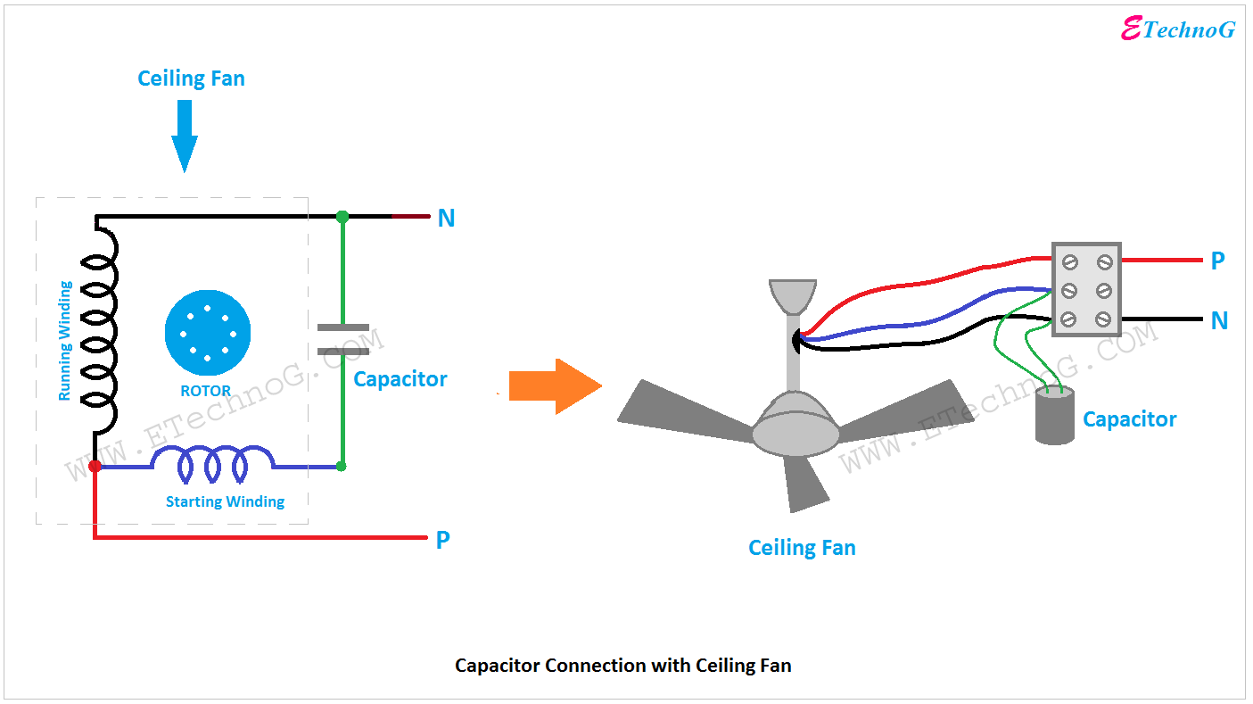
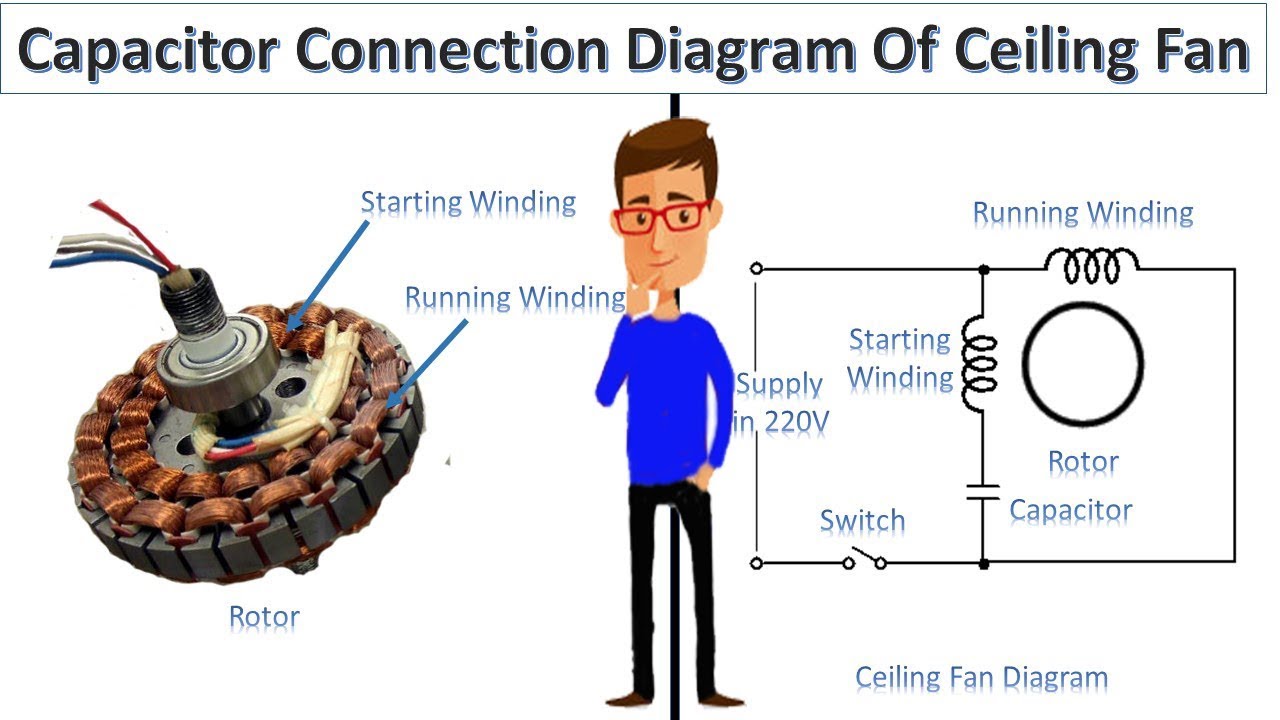
Capacitor connection diagram of ceiling fan Ceiling fan has a "capacitor start motor" in its inside. AC single phase capacitor start motor has two winding; one is starting winding and another is running winding. Fig-2: Ceiling fan capacitor connection diagram
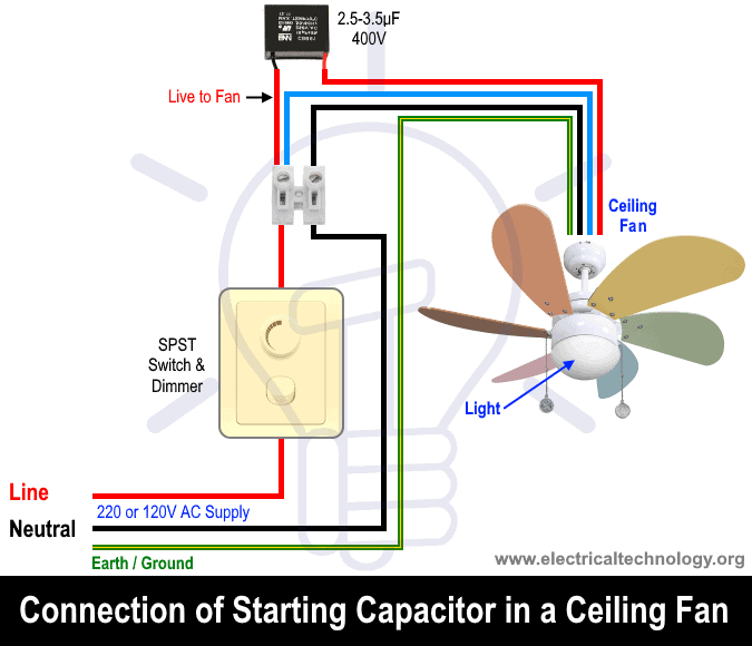
[Proper] Ceiling Fan Connection with Regulator, Switch and Capacitor ETechnoG
A fan capacitor wiring diagram typically contains symbols, lines, and arrows that represent the components connected in the fan capacitor circuit. The symbols represent the type of component and its function. For example, the circles may represent capacitors or coils, the rectangles represent switches, and the arrows represent electrical current.

Exhaust Fan Capacitor Wiring Diagram
17/03/2022 0 3471 Do you know 3 wire capacitor diagram for the ceiling fan? In this article, we are going to acquaint you with the ceiling fan capacitor wiring diagram. We can connect capacitor with ceiling fan very easily.
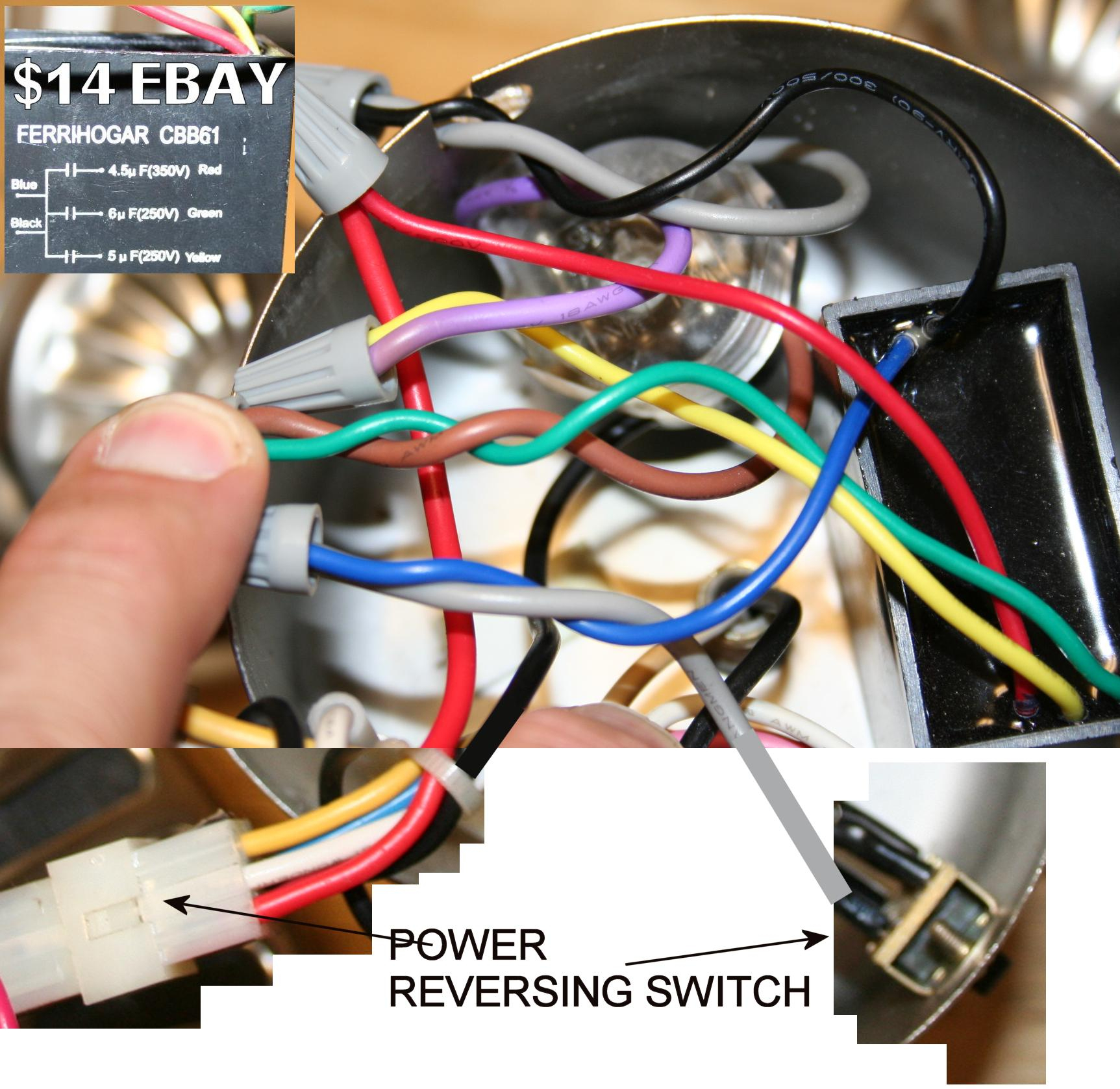
How To Replace a Capacitor in a Ceiling Fan? 3 Ways
Now in this, you will learn about the ceiling fan 5 wire capacitor and its diagram. 5 Wire Ceiling Fan Capacitor Wiring Diagram. In the ceiling fan, we use the 5-wire capacitor for speeds, low Med and High speed. On this type of capacitor, we have five wires, in which two is common and 3 other for different value capacitance microfarad. In the.

Cbb61 Fan Capacitor Wiring Diagram
As shown in the above ceiling 3 wire capacitor diagram red is common wire and yellow for 1.5 microfarad and Purple for 2.5 microfarad. However, IN SHA ALLAH in the further post, I will explain the fan 5 wire capacitor, regulating speed switch diagram, and replacement of the fan capacitor in the fan motor.

Wiring A Ceiling Fan Switch From Capacitor Pearl Schema
The 3 speed ceiling fan wiring diagram options below make it easy to wire/install a ceiling fan capacitor and fan. The wiring diagrams cover popular models manufactured by Hampton Bay, Harbor Breeze and Hunter but work for many other brands that also employ a capacitor in order to control fan speed using the pull chain.
15 Ceiling Fan Connection Diagram With Capacitor Robhosking Diagram
Now, let's dive into the wiring process. The first step is to identify the three wires coming from the ceiling fan motor. These wires are usually marked as L, 1, and 2. L stands for live or power supply, 1 and 2 are for different fan speeds. Next, locate the four wires on the new capacitor, two of which will be connected to the ceiling fan wires.

Fan Capacitor Connection Diagram
1 2 3 4 5 6 7 8 9 Share 412 views 1 year ago This post is about the ceiling fan connection with a capacitor diagram, or how to wire a ceiling fan with a one-way switch, speed control.
5 Wire Ceiling Fan Capacitor Wiring Diagram Wiring Diagram
Specifications Fan capacitor specifications include the following. Through-hole mounting type. Capacitance ranges from 1.5 MFD to 4 MFD (micro-Farad). The voltage rating is 440 VAC. The diameter is 27 mm. Tolerance is 5%. Cylindrical shape. The frequency is 50Hz. The number of phases - 1 phase. Temperature ranges from -25 to +85 Deg C

Table fan motor winding data with connection in hindi » Motor Winding Data
When choosing a capacitor for an electric fan, it is important to consider the capacitance, voltage rating, and temperature rating of the capacitor. Installing a capacitor on an electric fan is a simple process. Cooling Fan Sd Control Circuit. Winding Connection With The Capacitor Scientific Diagram. Is There A Wiring Diagram For The 40csfm 3.

Wiring Diagram Fan Motor Capacitor Schematic Power Capacitor Fan Down Main Circuit Circuitlab
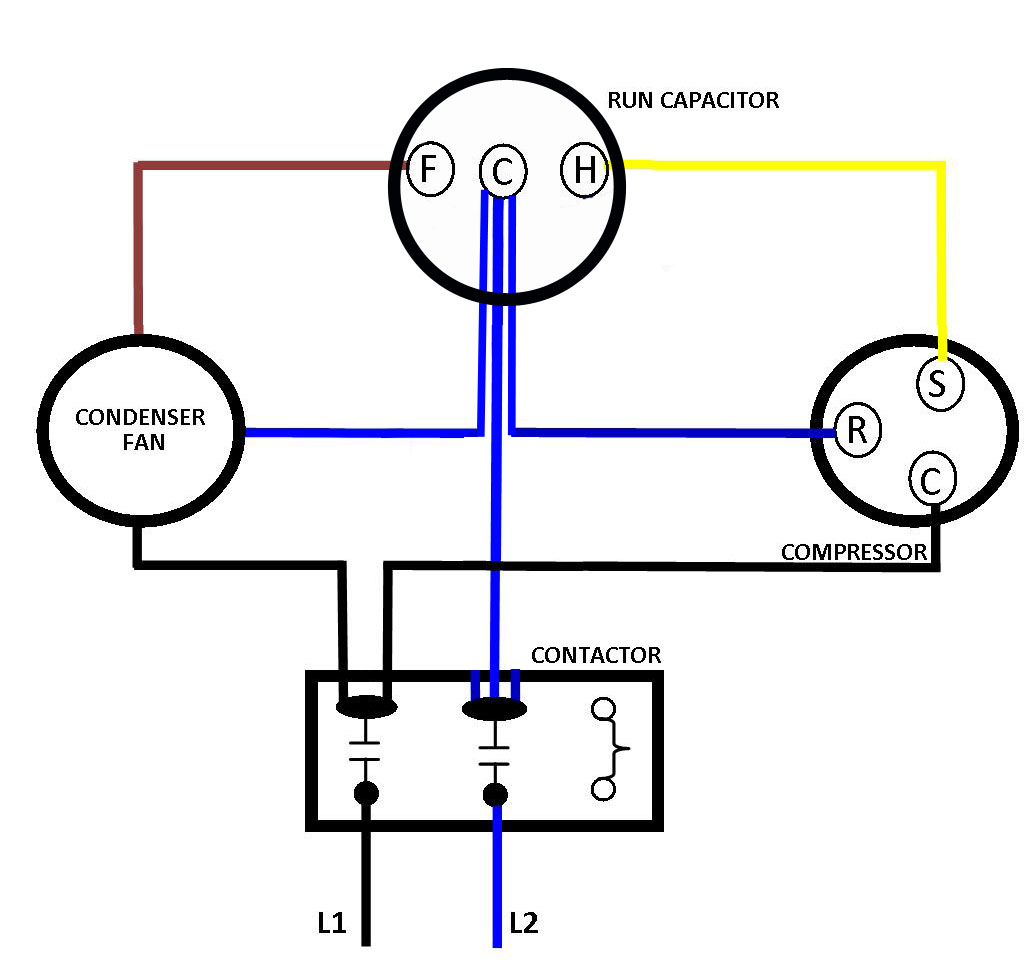
A C61 Ceiling Fan Capacitor Wiring Diagram will usually show two capacitors with red and black wires connecting to each other. The red wire runs from the power source to the fan motor, while the black wire goes from the fan motor to the capacitor. The diagram will also show the terminals on each capacitor, as well as the polarity of the.
LEGRAND Plate For SWD Socket 2G Sqr BS, Pearl Aluminum
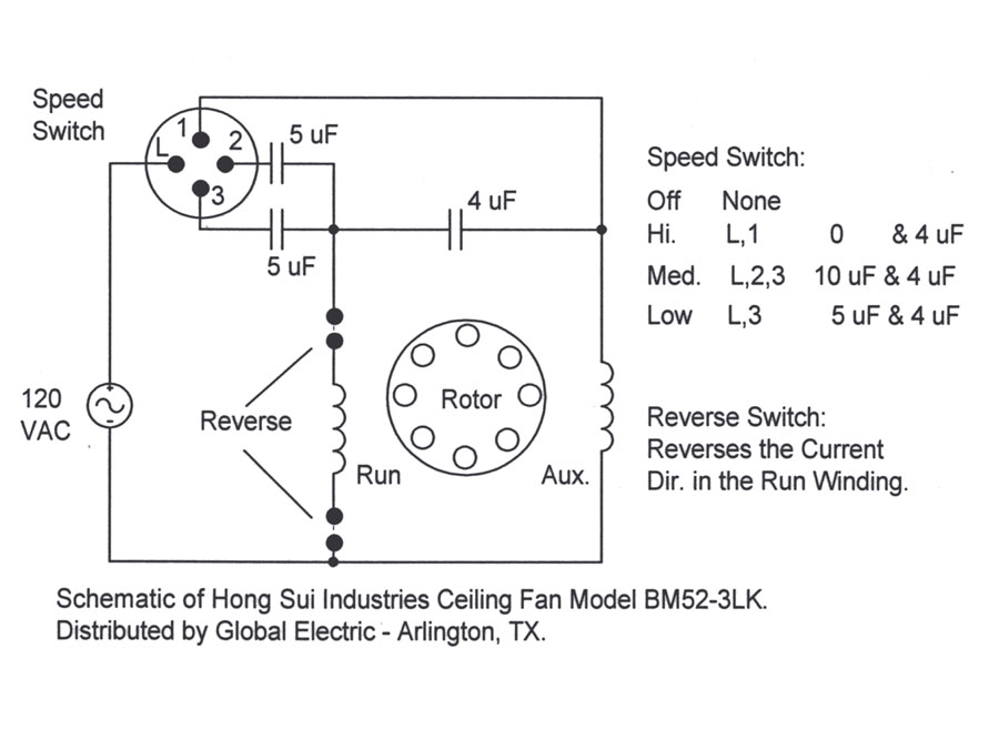
And the capacitor is connected between the "run" and "start". In the above ceiling fan capacitor wiring diagram, I have shown how to connect the capacitor to the ceiling fan, and how to wire a ceiling fan with a one-way switch and speed controller (dimmer switch). In the above diagram, I showed the running and auxiliary windings.
Ac Start Run Capacitor Wiring Diagram Wiring Diagram and Schematic Role
A Fan Motor Capacitor Wiring Diagram will show you how to properly connect the capacitors to the fan motor. Most commonly, these diagrams will show two capacitors connected in a series circuit. This is because the capacitors are used to increase the starting torque of the fan motor so it can start up more quickly.
5 Wire Ceiling Fan Capacitor Wiring Diagram
The capacitor will be connect as shown in the below ceiling fan connection with capacitor diagram. In the above ceiling fan connection with capacitor diagram , I shown the fan internally winding and capacitor connection.

Ceiling, Wiring Diagram, With Capacitor Connection Popular Ceiling, Capacitor Connection Diagram
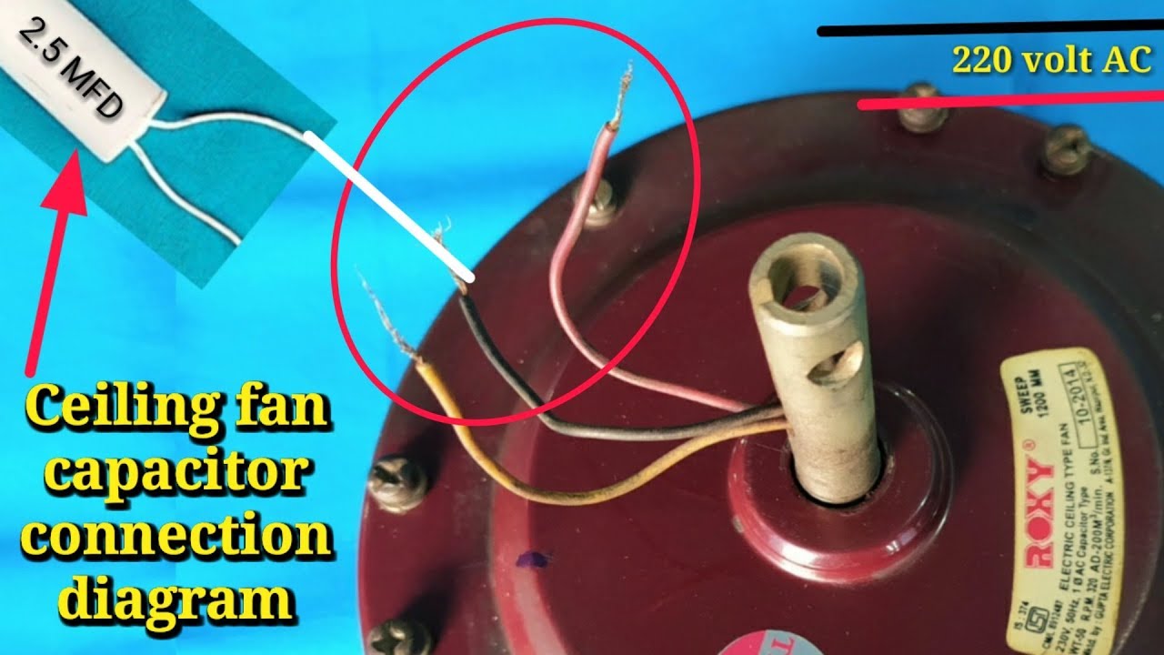
The ceiling fan capacitor wiring has become easy if you know about the start, run, and common connection in fan wires. As you know that ceiling fan has 3 wires which come out from winding. In this wire, we connect the electric power supply and capacitor. But the problem is which one is for the capacitor and which one is for the direct power supply.

230v Single Phase Capacitor Wiring Diagram Diagrams Schematics For Fancy Motor Run 11 Ac
Ceiling fan connection of 3 wire with capacitor—In this video, I'm going to show you how to connect a ceiling fan with three wires or with a capacitor. You w.